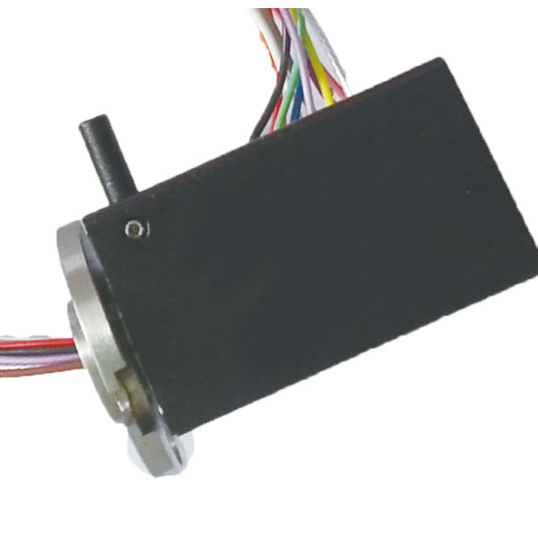
We know that when [Big Clive] puts up another video, the chances are we’re in for another fascinating look into a piece of tech on his bench. The latest is a slip ring assembly, and he gives it a teardown to reveal its secrets.
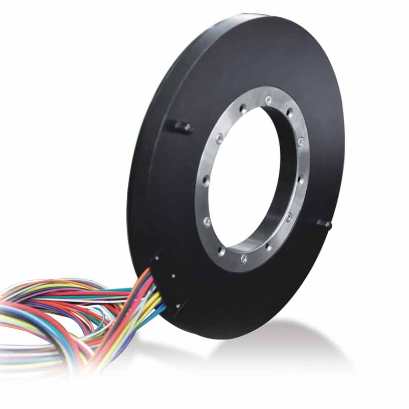
For most of us, the only place we encounter a slip ring is in some electric motors or alternators when it provides a connection via a conductive ring and a graphite brush from a fixed component to a rotating one. But they also appear as components in their own right wherever a rotating assembly needs an electrical contact, and it’s one of these that [Clive] has on his bench. It’s a compact unit with an impressive six conductors, and its manufacturer boldly claims that it’s good for mains voltages. We’re going with the verdict in the video below the break. That’s wishful thinking, given the size of the unit. High Protection Slip Rings

Inside is a rotor with six brass rings and a couple of decent little bearings, while the other half of the unit is a set of gold-plated spring contacts. There is extensive use of potting, and the verdict is that this is a surprisingly good quality component for the eBay price. We look forward to our community finding inventive uses for them. Having a ready-made unit sure beats making your own.
Continue reading “What’s In A Slip Ring?” →
Back in the old days, we didn’t have fancy digital clocks. No, we had good analog clocks with a big hand and a little hand, and if you wanted to know the time you had to look at the clock and figure out which number each hand was pointing at, or kind of pointing at. It wasn’t easy, and we liked it that way.
So now, along comes an analog clock that’s nothing but the hands — no dial, no numbers, just hands. How is such a thing possible? The clue is in the clock’s name: AKUROBATTO, and in the video below, which shows the acrobatic movements of the clock’s hands as it does its thing. Serial improbable-clock maker [ekaggrat singh kalsi] clearly put a lot of thought into this mechanism, which consists of the hands and a separate base. The hands are joined together at one end and powered by small stepper motors. The base has two docking areas, where servo-driven claws can grasp the hand assembly, either at the center pivot or at the tip of either hand. With a little bit of shuffling around at transition points, the hands sweep out the hours and minutes in a surprisingly readable way.
For as cool as the design of AKUROBATTO is, the internals are really something else. There are custom-built slip rings to send power to the motors and the Arduinos controlling them, sensors to determine the position of each hand, and custom gearboxes for the steppers. And the locking mechanisms on the base are worth studying too — getting that right couldn’t have been easy.
All in all, an impressive build. Whether displaying the time on a phosphorescent screen or a field of sequins, it seems like [ekaggrat] has a thing for unique clocks. Continue reading “Unique Clock Is All Hands, No Dial, And Does The Worm” →
A lighthouse beams light out to make itself and its shoreline visible. [Daniel’s] lighthouse has the opposite function, using lasers to map out the area around itself. Using an Arduino and a ToF sensor, the concept is relatively simple. However, connecting to something that rotates 360 degrees is always a challenge.
The lighthouse is inexpensive — about $40 — and small. Small enough, in fact, to mount on top of a robot, which would give you great situational awareness on a robot big enough to support it. You can see the device in action in the video below. Continue reading “Lidar House Looks Good, Looks All Around” →
For many of us who grew up in the 1970s, “VertiBird”, the fly-it-yourself indoor helicopter, was a toy that was begged for often enough that it eventually appeared under the Christmas tree. And more than a few of the fascinating but delicate toys were defunct by Christmas afternoon, victims of the fatal combination of exuberant play and price-point engineering. But now a DIY version of the classic toy flies again, this time with a more robust design.
To be fair to the designers at Mattel, the toy company that marketed VertiBird, the toy was pretty amazing. The plastic helicopter was powered by a motor located in the central base, which rotated a drive rod that ran through a stiff tether. Small springs in the base and at the copter acted as universal joints to transmit power to the rotor. These springs were the weak point in the design, especially the one in the base, often snapping in two.
[Luke J. Barker]’s redesign puts a tiny gear motor in the aircraft rather than in the base, something that wouldn’t have been feasible in the original. To address the problem of getting electrical power from the base to the aircraft, [Luke] eschewed an expensive slip ring and instead used a standard 3.5-mm audio jack and plug. The plug serves as an axle for the main gear in the base that powers the copter’s rotation; sadly, this version doesn’t tilt the aircraft mechanically to control backward and forward flight like the original. A pair of pots with 3D-printed levers control throttle and flight direction through an Arduino; see it in action in the video below.
These pages abound with rotorcraft builds, both helicopters and multirotor. We appreciate all manner of flying machines, but this one really takes us back.
Continue reading “Classic Toy Helicopter Flies Again As DIY Version” →
A couple of Christmases ago, [Nick] got tired of trying to evenly decorate his giant fake tree and built an MDF lazy Susan to make it easy as eggnog. But what’s the point of balanced decorations if one side of the tree will always face the wall? This year, [Nick] is giving himself the gift of a new project and motorizing the lazy Susan so the tree slowly rotates.
The saintly [Nick] decided to do this completely out of the junk box, except for all the WS2811 RGB LEDs on order that he hopes to synchronize with the tree’s movement. He started by designing a gear in OpenSCAD to fit the OD of the bearing, a task made much simpler thanks to the open-source gear libraries spinning around out there.
It was hard to get slow, smooth movement from the NEMA-23 he had on hand, but instead of giving up and buying a different motor, he designed a gear system to make it work. Our favorite part has to be the DIY slip ring [Nick] made from a phono connector to get around the problem of powering a rotating thing. This is a work in progress, so there are no videos just yet. You can watch [Nick]’s Twitter for updates.
[Nick] didn’t specify why he chose to use WS2811s, but they have gotten pretty cheap. Did you know you can drive them with VGA?
Via Adafruit’s CircuitPython newsletter
Rotating mechanisms can be a headache when it becomes necessary to deliver power through them. [Igor Brkic] faced just such a challenge when creating his double-pendulum build, and solved it with a little DIY.
The project is known as KLAATNO, inspired by the Croatian word for pendulum, klatno. It’s a mechanical installation piece, consisting of a power-assisted pendulum, with a second pendulum fitted at the end of the swinging arm. A 24 volt geared motor is used to drive the assembly. It’s controlled by an Arduino Pro Mini, which measures the back EMF from the motor terminals to determine the speed and direction of the motor’s movement.
To make the installation more visually striking, EL wire was installed on the swinging arms of the twin pendulums. This required the transfer of power to the rotating assembly, which was achieved through the use of custom made slip rings. Copper sheet is used in combination with a flexible metal wire sourced from a guitar string. It’s not as low-friction as [Igor] would like, but it gets the job done.
It’s a fun installation that would be perfectly at home in the common area of any university engineering building. Of course, our favorite pendulums are of the siege weapon variety. Video after the break.
Continue reading “Double Pendulum Uses Custom Slip Rings” →
Persistence of vision projects were once all the rage, judging by a quick review of the literature here on Hackaday. They’ve tapered off a bit lately, but this impressive full-color globe display might just kick-start some new POV projects.
Built as a final project for an EE course, [Evan] and [Kyle]’s project is more about the control electronics and programming than the mechanical end of the build. Still, spinning a 12″ ring of 1/4″ thick acrylic with a strip of APA102 LEDs glued to the edge takes some thoughtful engineering. While the build appears sturdy, [Evan] does admit to a bit of wobble under full steam, which was addressed by adding some weight to the rig. We wonder if mounting half the LEDs on each side of the ring to balance the forces wouldn’t have worked better. True, it would have complicated the coding for the display, but maybe that would have been good for extra points. In any case, the display turned out well and the quality of the images is great. And as an aside: how awesome is it that we live at a time when you can order a six-circuit slip-ring for a project like this for less than $20?
It’s the end of the semester and we love seeing the final projects that have just made it across the finish line. This globe is one, yesterday we saw a voice-controlled digital eye exam, and if you have or know of a final project, don’t forget send us the link!
If POV globes are your thing, be sure to set the Hackaday WABAC machine a few years and check out this Death Star design from 2012 or this globe from 2010.

Waterproof Slip Ring Capsule By using our website and services, you expressly agree to the placement of our performance, functionality and advertising cookies. Learn more
